Porcelain Insulator News
by Jack H. Tod
Reprinted from "INSULATORS - Crown Jewels of the Wire", November 1978, page 8
The following feature is a description of the manner in which the insulator
drawings for the Universal Style Chart have been made over the years. Collectors
who are familiar with the details of this have found it interesting, so it may
be of interest to you also. The "shadow profile" method of making drawings
without shipping insulators back and forth is the method we currently use to
make drawings of all newly discovered items, and collectors should make note of
it.
When I started in 1970 to research porcelain insulators and create a style
chart of the various shapes so we could list and mail trade them like we were
already doing with glass insulators via the CD- Chart, I never dreamed this
would result in the eventual making of nearly 1500 drawings. I did know from
what I had already seen that there would be quite a large number of drawings
required. Even before I made a single drawing, I first devised several methods
for efficiently making large numbers of accurate and uniform drawings.
Regardless of the method used, it was desired to first obtain drawings which
were uniformly made at 1:1 scale (actual size) and that these could subsequently
be reduced to 1/4-size for the published Universal Style Chart.
The biggest
original source for the insulator drawings was the large number of old
insulator catalogs that are still extant. Nearly all insulator manufacturers
were prolific issuers of detailed catalogs with reasonably good mechanical
drawings of the various items they made, including insulators. Most manufacturers
secured catalog issues of all the competitors so they knew what and where the
latest action was, and it was very fortunate that manufacturers tend to be pack
rats in the saving of old catalogs -- all because they might later be useful as
a reference to past events. In any event, I wasn't lacking for reference
material in most cases.
It was obvious from the catalogs I had already seen that
all these drawings would have to be completely redrawn to a uniform standard. Even within a single company catalog, the drawings
sometimes varied greatly in
scale and in depiction. It appeared easiest to make new drawings by transferring
the catalog information to new drawings with a photographic method, so that is
what I devised. Furthermore, making the drawings by first photographing the
catalog pages would allow me to speedily collect all the required data
when I visited all the manufacturers on eastern research trips.
During my first extended research trip to the eastern insulator manufacturers
in the spring-summer of 1971, I photographed the pages of pin type insulators
from countless old catalogs. In cases where the company had duplicate catalogs,
or if I could otherwise talk them out of a copy of a given one, I just brought
that home and later photographed the pertinent pages. I also was able to merely
Xerox pages of many catalogs at some companies and then later photo these when I
returned home (a stack of Xerox pages about 3" tall!). In all, I eventually
had taken over 1200 photographs of pages from insulator catalogs -- just the
pages showing unipart pin types, and not any of the pages already at 1:1
scale.
My photo setup was simple. The camera was tripod mounted to shoot vertically
down onto the catalog pages, carefully plumbed to vertical alignment to eliminate
annular distortion. With black-white film and reasonably slow exposures, regular
room lighting was always sufficient. My projection system required use of a 3X
lens multiplier on the camera whenever shooting drawings at scales smaller than
1/5 size.
I had all this film developed only (no prints), and then I ironed in each
frame in standard slide mounts for projection. I then projected these
"slides" in the setup shown below.
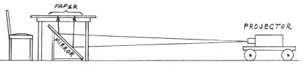
The beam from the projector traveled horizontally to a large mirror which
reflected the beam upward to the surface of a glass-topped table. A sheet of
bond drawing paper on the table served as the light diffuser -- all details from
the catalog drawing appearing as illuminated lines and numbers on the drawing
paper. The projector was moved back and forth in the room on a small cart (with
remote push-pull arrangement and remote focus control) to make the projected
image exactly 1:1 scale on the drawing paper. In some cases, the reflecting
mirror had to be slightly rotated and/or tilted to remove distortions ever
present in the catalog drawings and possibly resulting from my photographing
Xerox pages instead of the catalog pages themselves on some occasions.
I then made a blue-line tracing of the illuminated image of the insulator,
doing all several hundred of these in one session. This involved sitting in a
dark living room for 3 to 4 weeks -- not to mention using up 4 of those
"life" projector bulbs. I had previously spent nearly 3 weeks figuring
out from all the data which insulators in all photos had to be drawn up. Even at
that, many drawings were eventually completed which were not used in the Style
Chart because they so closely resembled other drawings.
The stack of 400+ blue-line drawings were then all inked in another mass
production system lasting several weeks -- all the horizontal lines, all the
vertical lines, the curved lines, the threads, the cross-hatching, finally
dimensioning. This used up 2 reams of bond paper, 3 bottles or India ink and two
perfectly good ruling pens supposed to last forever. My wife brought me more
coffee and no-doze pills every few hours during this long stretch.
The second large source of drawings for the Style Chart was that of insulator
specimens themselves. We naturally couldn't locate every conceivable old
catalog, and many items were made which weren't catalog items anyway. Once
again, it was necessary that I devise at the outset a method for making accurate
drawings from specimens. There are several ways this can be done, each with
varying degrees of efficiency and accuracy. My method is described below.
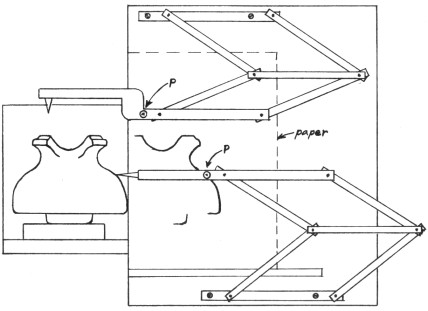
I designed and built the profiling machine shown above. The two movable
linkages each cause a pencil point (P) to trace on a sheet of drawing paper the
same path that the pointer follows as it moves over the contour of the
insulator. The bottom linkage is used to copy the side profile of the insulator;
the top linkage is used for the crown profile. The linkages and the pointers
have adjustments (not shown) which allow close calibration of the linkages -- so
that each traces an identical path on the paper for a given part of the
insulator contour over which the pointers move.
It doesn't show in the simple plan view of the machine, but the table with
the linkages and drawing paper is elevated 4" above the smaller portion at
the left on which the insulator is positioned. The insulators (varying in size)
are blocked up to fix their axis in the same plane as the pointers.
After the crown and side profiles have been drawn (as in the sketch above),
the drawing paper is shifted, and the insulator is rotated 90 degrees to the
left. The bottom linkage and pointer are then used to draw on the paper the
exact profile of the insulator's "guts" (petticoats etc.).
The completed drawing in then made from this worksheet on a separate paper
with the use of regular drafting instruments and a light-table. Centerlines are
drawn in for both the outer profile tracing and the "guts" tracing.
These are matched with a centerline on the final drawing sheet, allowing each
element to be added in turn to the drawing. The pin hole depth is merely
measured, and the threads are later added to the final drawing with a master
thread-drawing on the light table setup.
The entire machine and associated items are compact and fit into a relatively
small box which was, in turn, made to fit into a given spot in my camper. It has
been very handy for making drawings of specimens when I was traveling to shows
and visiting distant collectors.
At first, collectors were mailing new specimens to me for the purpose of
making drawings and then returning the insulators by mail. This not only was
expensive and involved delays, but collectors were reluctant to mail very rare
items back and forth just to make drawings. Thus, I soon devised a method for
making the drawings by "remote control" to eliminate mailing
specimens. This method involves merely the making of a shadow profile of the
insulator and making certain measurements. It is very simple and is the sole
method we now use for making drawings from specimens reported through the mail
by collectors.
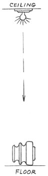
Place the insulator on its side on a piece of paper on the floor directly
below a ceiling light. Plumb the vertical line with a piece of string. Unscrew
all but one bulb in the ceiling fixture to eliminate multiple shadows. Block up
the crown of the insulator with some little item so that the insulator's axis is
parallel with the floor and so it will stay put that way without being
held.
Now get down on your tummy and carefully trace onto the paper the shadow cast
by the insulator. Do not tweak up this profile tracing or add any
dimensions or unseen details to it. Leave it raw just as you traced it. On a separate
paper, you can make a sketch of the insulator to record various dimensions which
you can measure with a regular scale -- width, height, pin hole depth,
centerline diameter of interior petticoat(s), height of threads collar, height
of recessed petticoats above the base, height above base of slots between
petticoats, etc. Also sketch separately (not on the profile) what the crown
groove cutaway detail looks like from the front, or simply compare the crown to
one that looks the same way on any of the U- numbers in the present Style
Chart.
After you send the profile tracing and sketch with dimensions to me, I can
make an accurate drawing. I first establish a true centerline which is corrected
for the small parallax error (the profile being slightly larger than the
insulator due to the divergence of the light from ceiling bulb only 7-1/2'
distant). I then use the profile on a light table to generate the entire outline
of the insulator, eliminating any parallax error as this is being done. The
interior ("guts") details are laid in from your dimensioned sketch to
complete the drawing. You get an immediate copy of it to check for
accuracy.
It takes you only about 5 minutes to make the profile and measure the
dimensions, and it takes me only 5 minutes to make the completed drawing.
Drawings made by this method have in most cases turned cut to be essentially
identical with those that could have been made had the specimen been placed on
the profiling machine! And with mach less fuss and postage costs.
The small parallax error can be essentially eliminated altogether by using a
very distant light source. Alas! The sun's distance approaches infinity for this
purpose. For anyone wanting the ultimate system for making errorless drawings of
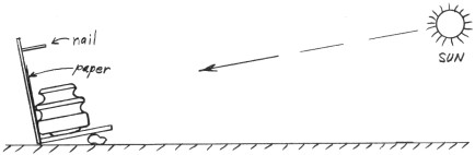
insulators (or anything) by shadow profile, use the sun as the light source (see
above sketch). Just nail two pieces of scrap board together at a 90 degree
angle. Tack a long finishing nail into the vertical board exactly perpendicular
with the surface (check vertical with a square). Tape a sheet of paper onto the
vertical board behind the insulator.
Now take this contraption out in the yard, unless you happen to live in a
glass house. Prop un the bottom board and rotate the whole thing until it points
directly at the sun where the nail casts no shadow at all. Now trace the shadow
profile onto the paper. As opposed to profiles made with a ceiling light inside,
this sun shadow is super crisp and intense. You may even need sun glasses to
look at it.
Due to the sun's nearly infinite distance in these terms, there is zero
parallax error in this method (a 4-1/2" insulator will cause a shadow exactly
4-1/2").
One slight error creeps in due to the habit of the sun traveling across the
heavens while you're down on your knees tracing the shadow, but this error is
insignificant. As you can readily calculate, the shadow of a point will move on
the paper only 0.00436" per minute per inch the point is away from the paper.
Thus, if you take a whole minute to trace the profile of an insulator with
8"
diameter (contour points 4" from paper), the shadow will move only 0.01744"
(about 1 /64th inch) during that time. Your pencil line is even wider than that.
The maximum left-right error (insulator width) would be from shadows at noon;
the maximum up-down error (insulator height) would be from shadows in early
morning or late afternoon.
Using the sun for making shadow profiles is much easier when the insulator is a large one
(6" diameter or larger). When making
the profiles of larger insulators with a ceiling light, it is difficult to
properly position them, and serious parallax distortion and size discrepancies
start to appear. Once I started using the sun method, I now use it for all the
items. It's easier to step out the side door to the sun than it is to move the
desk over and unscrew the other bulbs in my ceiling fixture. But the ceiling light is
still recommended for you guys who live in 9th floor apartments and for those who
step outside and find 6' of snow or the sun occluded by perpetual clouds (or
smog?).
That completes the brief description of ways in which we have made drawings
of pin types for the Universal Style Chart. There are currently 943 different
shapes shown in the Style Chart, plus several more added in the past year. A
rough estimate of the number of these drawings made by each of the above methods
is: 40% by photographical projection, 45% by profiling machine, 15% by shadow
profiles made by collectors. Additionally, I have made several hundreds of other
drawings in the aggregate by all three methods and which are not in the
Universal Style Chart for various reasons -- foreign types, too close to other U-
numbers already listed, etc.
If you someday get the urge to make a drawing of some odd insulator
yourself, the method of doing this from the shadow profile and measured
dimensions is described in detail on pages 7-10 of the Sept 1972 Crown
Jewels.
Since some of you may not have that issue, here's a brief description.
Establish a
true vertical centerline on your shadow profile. If the sun was used as a
light source, the centerline is in the center of the profile. If a ceiling light
was used, the shadow should be a bit bigger than the actual insulator. Use only
the right-hand side of the profile, and move the centerline a hair to the right
to make its distance to the right side of the profile equal half the measured diameter of the specimen.
Now you will need to make the drawing on a "light table". You won't
have that, so construct one by setting a sheet of plastic or glass on two stacks
of books and placing a lamp underneath it (or use a glass-topped table). As a
substitute for those born with several extra hands to hold the work, you can use
the living room window as a light table.
Place your shadow profile with the added
centerline on the light table, and lay a sheet of clean paper over it. Draw in
the centerline on the clean sheet. Trace the right-hand side of the profile and
the right-hand half of the insulator crown and base onto your drawing sheet
(ignoring completely the left-hand half of your shadow profile). If the
insulator was large enough to cause parallax error in the profile, make your
drawing agree in height with the actual specimen. Align the top edge of the
profile with the top edge of your new drawing when you are tracing the top
portion; align the bottom part between tracing that; split the difference when
tracing the center part of the insulator's side.
Now turn the original profile
sheet over so that the right side of it becomes its left side (don't turn your
drawing sheet over). Place the drawing sheet on the profile paper and once again
align its centerline with the other centerline. Repeat the above process of
tracing the original profile onto your drawing sheet to complete the left-hand
side.
To depict both the external and internal appearance of the insulator as in
the U- Chart, draw in the crown details on the portion to the left of the
centerline, and show the right-hand side in cross-section. Lay in the various
points by measuring the specimen -- pin hole depth, petticoat placement, etc. The
internal details are far less important than the actual insulator contour, and
accuracy isn't really important on interior.
When reporting a new pin type
specimen to me for use in the Crown Jewels column and/or for addition to the U-
Chart, you can make a complete drawing of it for your own amazement, but please
send to me a raw, undiddled-with shadow profile and a separate sketch
showing the
measured dimensions. I will not put any item in the Universal Style Chart unless
I an certain the drawing is reasonably accurate. Some of my regular
correspondents can make drawings even better than I can, but some others just
don't have a flair for it.
INSULATOR MARKINGS
Collectors continually send us reports of various insulator markings, and
we have described a number of times easy ways to accurately show these markings.
Seems from some recent transmissions to us, we need a refresher course on this.
We use foil impressions to record embossed or incuse types of markings.
Cut out a
small section of new, unwrinkled aluminum foil from the kitchen roll. Hold this
down over the marking and repeatedly push down hard on it with a worn and rounded eraser on
the end of a wooden pencil. Keep doing this all over the design until every detail
is brought out sharply on the foil. To practice, take a new penny from your
pocket and make its foil impression. If every detail down to the last whisker on
Lincoln's face isn't as sharp on the foil as it is on the coin, you must be
doing something wrong.
Now lay the completed foil on its back on the table and
completely fill the back of the design impression with a fairly deep puddle of
Wilhold (Elmer's) glue. Allow this to set until the glue dries thoroughly hard
(may take several days). To mail a foil, lightly tape one end of it to your
letter in a position where, when the letter is folded, the foil will not fall
under the stamp canceling roller. It works best if you first fold the letter to
fit your envelope, then unfold it to tape the foil in the spot which will be in
the lower left corner of the envelope when refolded and inserted in envelope.
In
many cases, even with well made foils, certain elements of the marking which are
clear on the specimen may be so weak (or filled with glaze) that they don't show
well on the foil. In that case, always include a separate sketch of the marking
to show items (letters, periods, etc.) which didn't register clearly on the foil
impression.
To record flush markings which won't make foil impressions
(underglaze ink markings, incuse markings filled with glaze), proceed as
follows. Place a piece of cellophane over the marking, and trace the marking
with a sharpened wax pencil. To preserve the marking, completely overlay it with
a strip of clear Scotch tape. alternatively, transfer the wax marking on the
cellophane to paper by putting paper over the cellophane on a light box and
tracing it with a pencil (or use a room window if you don't have a light box).
Carefully
check your recorded marking against the actual specimen to catch any detail
(serifs on letters, periods, etc.) that you missed.
The nice part about using
one of the above methods when reporting new markings to us is that the foils
don' t lie! For some reason, people tend to look at the marking on a specimen
in their hand and yet write down on paper a completely different marking than
what their eyeballs are looking at. We get a report of a specimen with a marking
of "PATENT 8-25-15" when the actual specimen marking was "Patent
May 25,
'15". Later, of course, we get more reports from others that they also have
this item "except that it is marked 'Patent May 25, '15'". Best to get
it right the first time. Even if you report such word markings without sending a
foil impression, please try to copy down the marking exactly as you see it
proper types of capital or small letters, all the periods, etc.
- - - - - - - - -
Because of this feature article, some porcelain news items and letters have
been deferred to the following issue of CJ.
| 
)
)
)
)